Date | 2016/09/01
CALIN Technology Eliminated Weld Lines on a Projector Lens Using Moldex3D
 |
|
Incorporated in 2002, CALIN’s high-ranking executives possess years of work experience and expertise. They provide all types of optical lenses and all customized development services. The main products of the company include automotive camera, security camera lens, projector lens, digital camera lens, DSLR, industrial lenses, and medical endoscopy lens. CALIN has continuously oriented the high quality in optical lens and enhanced the core technologies to meet all the needs of customers. (Source: http://www.calin.com.tw/eng/index.php )
Executive Summary
CALIN Technology applied Moldex3D to predict the hesitation and weld lines on their projector lens product. Through the simulation analysis, CALIN Technology was able to adjust and optimize the process parameters prior to real manufacturing to solve the weld line problem and improve product shrinkage.
Challenges
- Obvious weld lines
- To reduce cycle time
- Uniform residual stress
Solutions
Utilizing Moldex3D Advanced to obtain optimum process settings in order to successfully resolve the product’s problem
Benefits
- Eliminated weld lines
- Achieved 98% yield rate
- Reduced mold trials and costs
Case Study
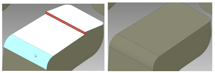
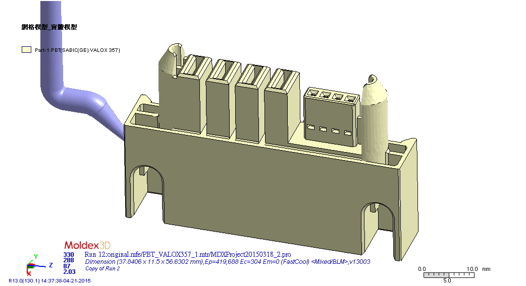
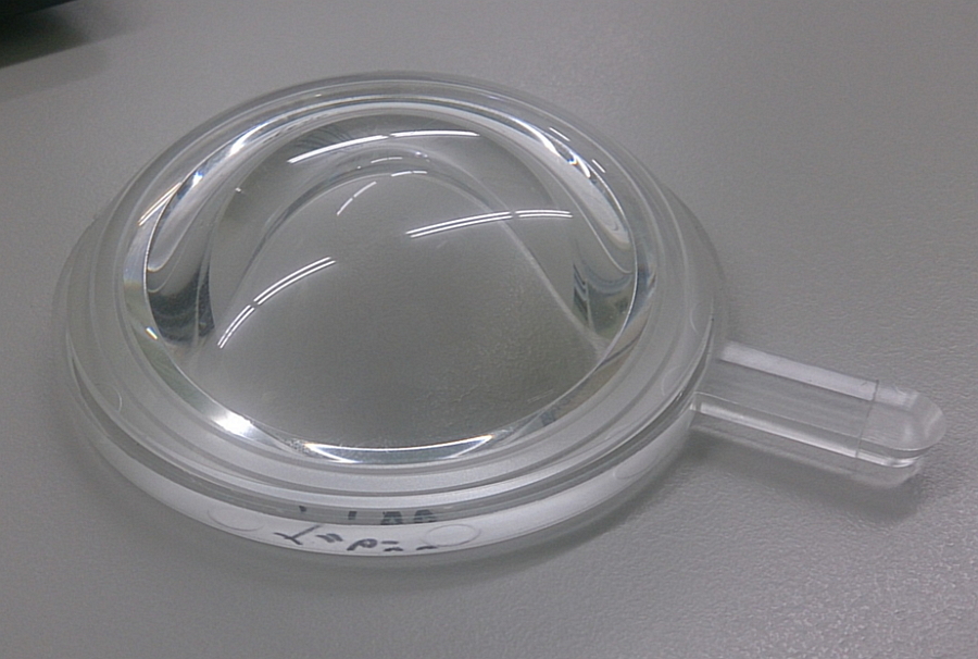
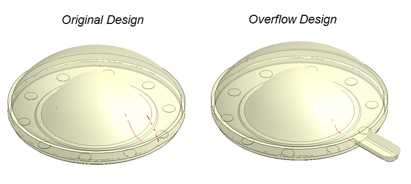
The objective of this case is to solve the weld line issue and reduce the cycle time of a projector lens product (Fig. 1). CALIN Technology decided to create overflow region and conformal cooling channels in order to achieve the goal. Although there are various methods to design the overflow zone and conformal channels, most of them would cost substantial mold production fees and time. Therefore, CALIN Technology utilized Moldex3D to simulate the molding scenario of the original design, overflow design, and conformal cooling channel design before an actual molding in hopes of achieving the most ideal design without excessive production cost.
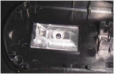
![calin-technology-eliminated-weld-lines-on-a-projector-lens-using-moldex3d-1]()
Fig. 1 The projector lens product in this case
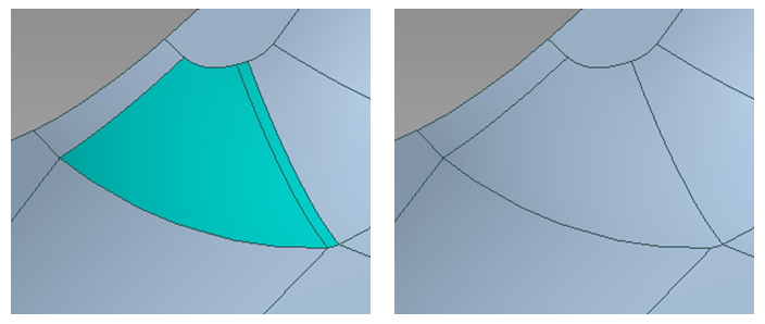
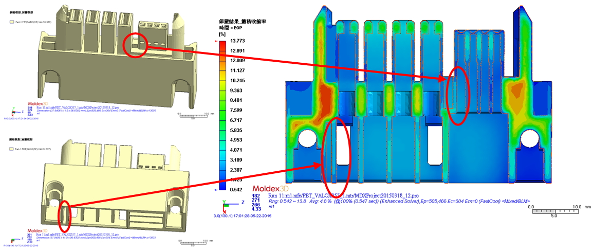
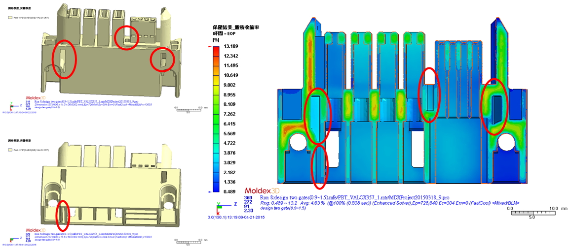
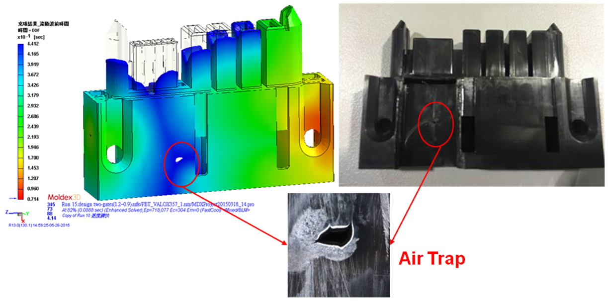
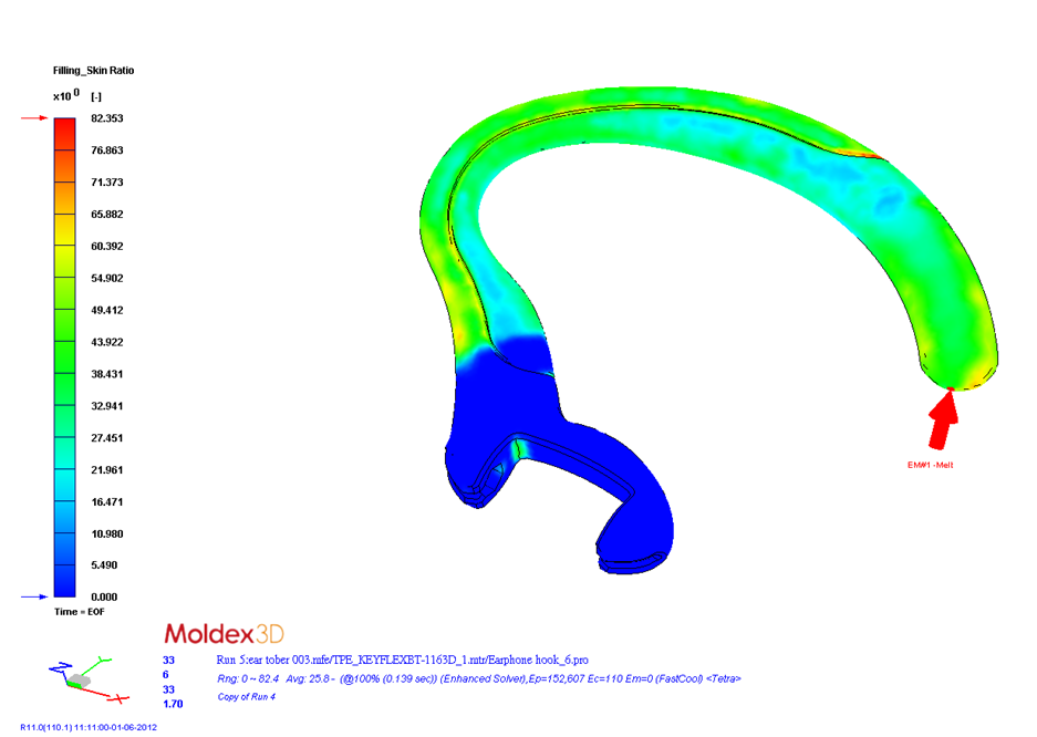
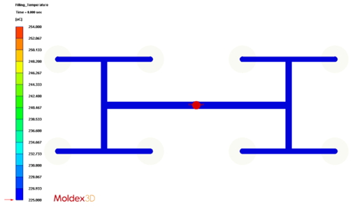
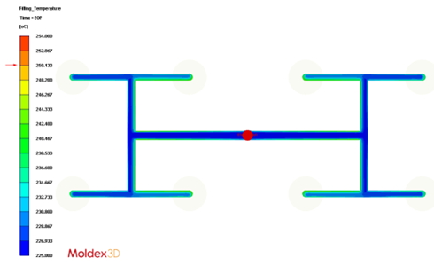
Through the simulation results, CALIN Technology found out that in traditional injection molding, weld lines would occur in the main region of the part and it might cause potential risks of product deformation. Furthermore, this molding defect would have a direct negative impact on the product’s functionality and physical appearance. Thus, CALIN Technology added an overflow region in the cavity in order to solve the weld line problem. According to Moldex3D simulation results of the revised design, the weld lines disappear in the obvious regions (Fig. 2).
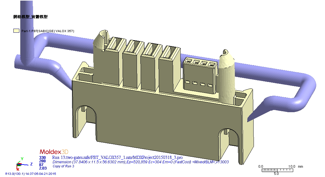
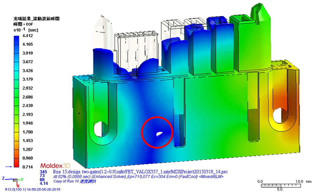
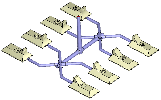
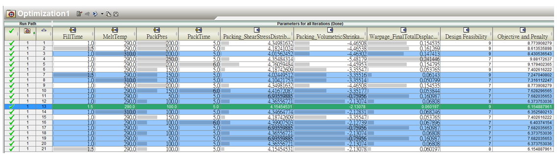
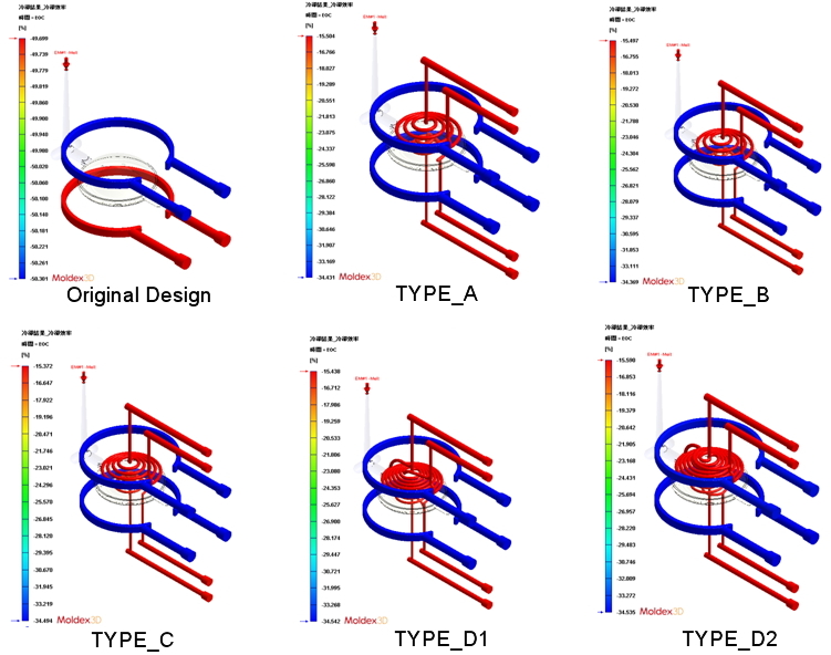
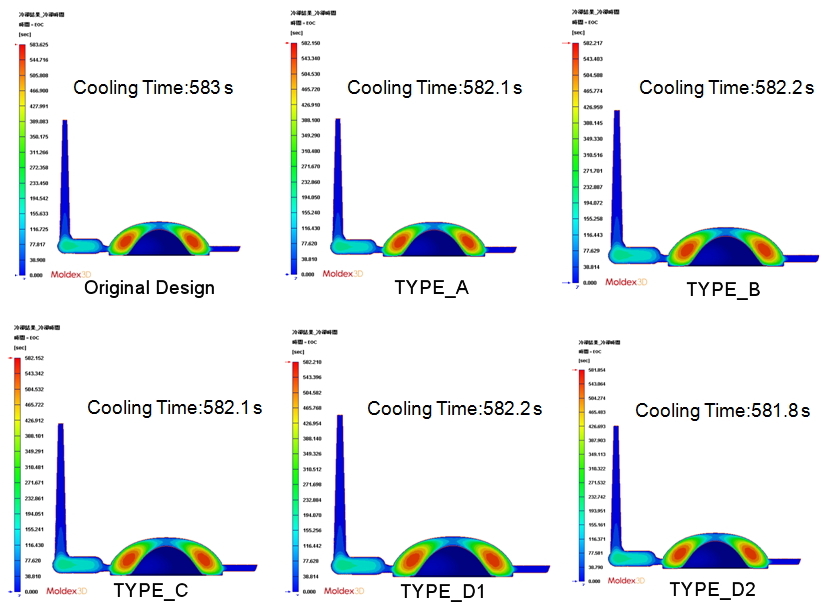
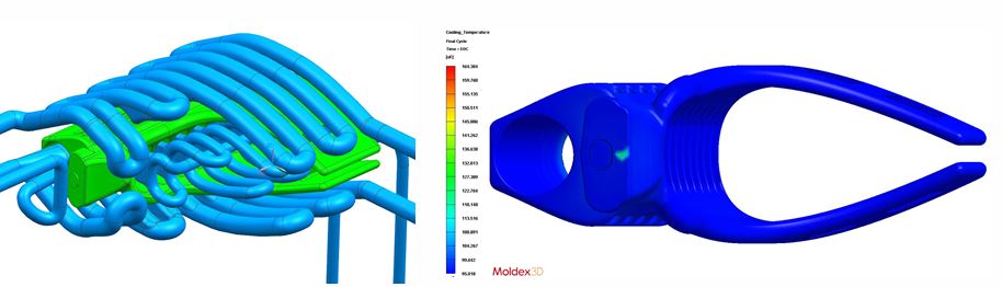
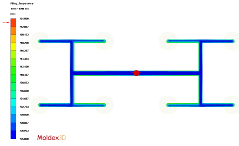
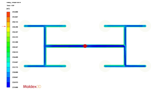
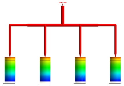
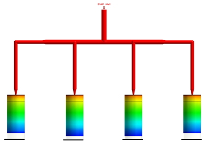
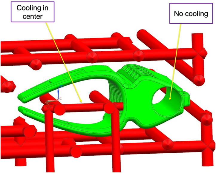
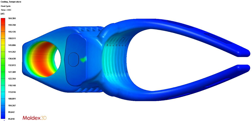
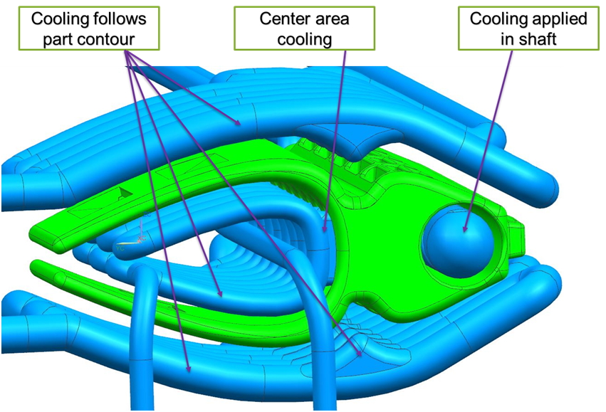
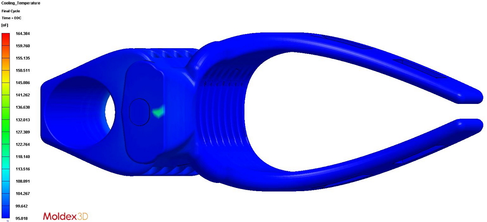
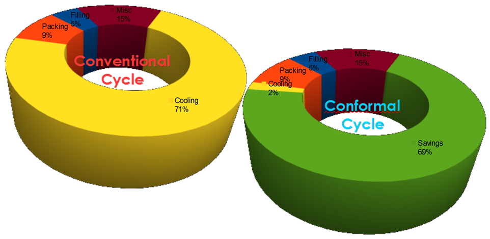
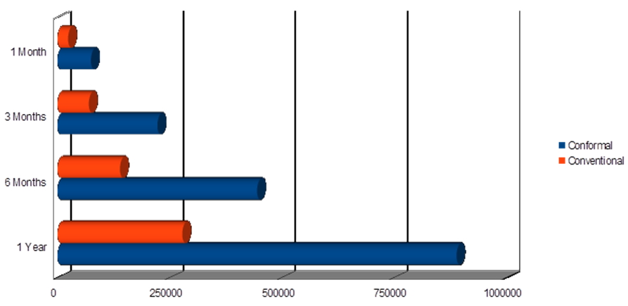
Next, to reduce the cycle time, CALIN Technology proposed using conformal cooling channel designs (Fig. 3). Through Moldex3D simulation results, the cycle time of revised designs does not show a significant improvement compared with the original design (Fig. 4), so there is no need to change the design of cooling channels.
![calin-technology-eliminated-weld-lines-on-a-projector-lens-using-moldex3d-2]()
Fig. 2 The weld line issue in the revised design with an overflow region has been improved
![calin-technology-eliminated-weld-lines-on-a-projector-lens-using-moldex3d-3]()
Fig. 3 CALIN Technology proposed using conformal cooling channel designs to reduce the cycle time
![calin-technology-eliminated-weld-lines-on-a-projector-lens-using-moldex3d-4]()
Fig. 4 The cycle time of revised designs does not show a significant improvement compared with the original design
Results
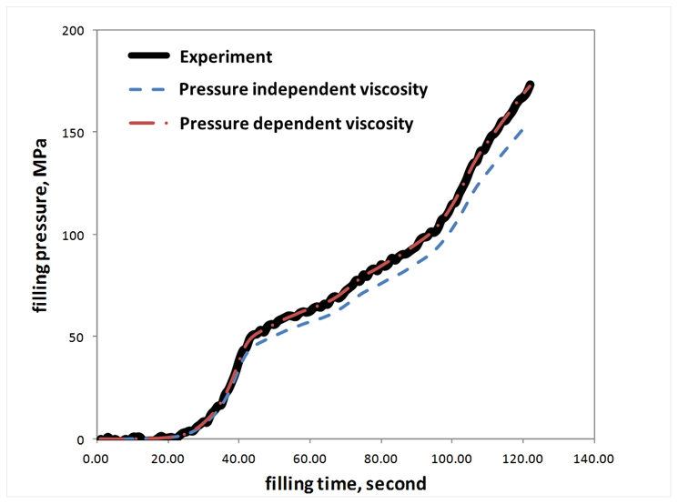
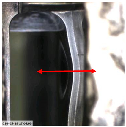
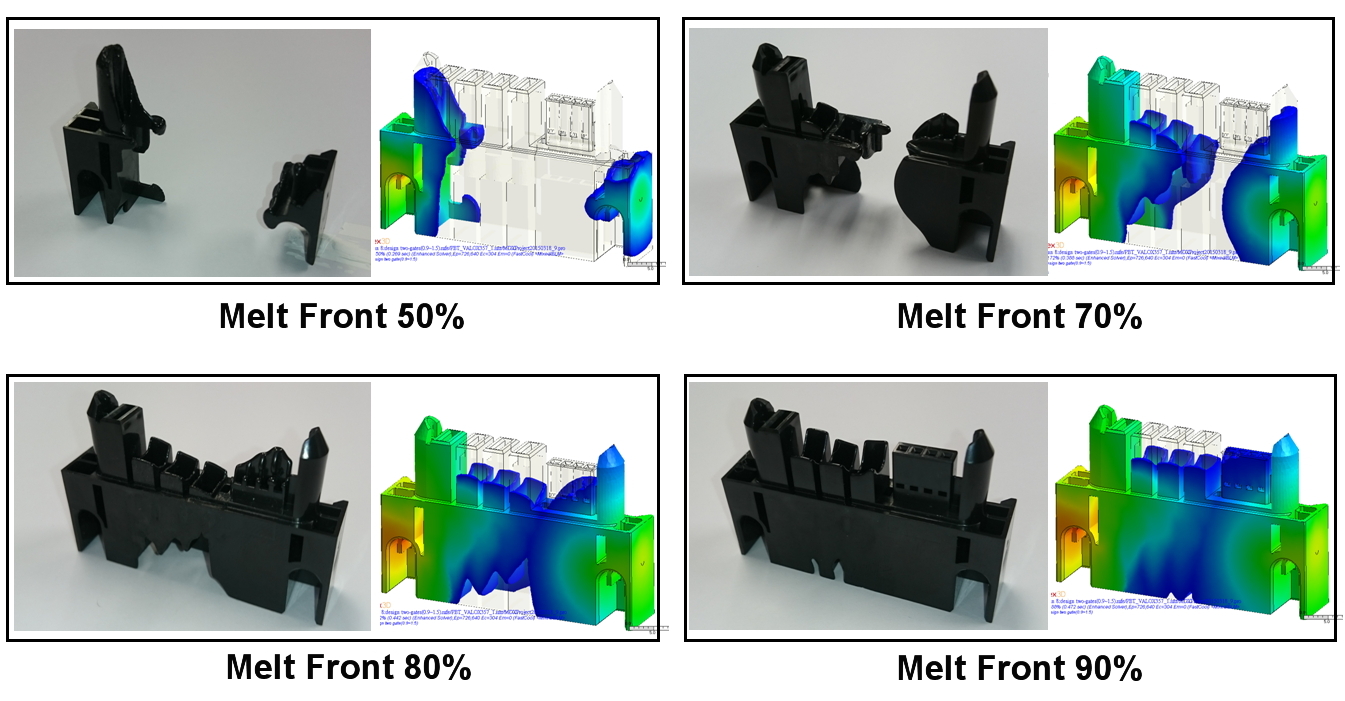
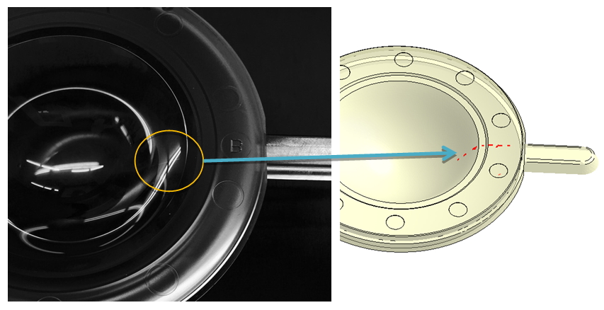
Through Moldex3D analyses, CALIN Technology could clearly understand the filling behaviors and predict weld line locations before an actual production. The accuracy of Moldex3D simulation analyses were also validated by the actual mold-trial results (Fig. 5). In the end, CALIN Technology was able to successfully solve the manufacturing issues and optimize their product and mold designs.


 under the list to find all steps within threshold. Use
  and other navigation tools to zoom current target and click Remove Steps
  below and choose a face near the step to fit.