Quantcast
Channel: Moldex3D :: Plastic Injection Molding Simulation Software
Viewing all 736 articles
Browse latest View live

PLASTICS-IN-MOTION 2017

$
0
0

Moldex3D is proud to announce that we will participate in PLASTICS-IN-MOTION 2017, a major industry event held on June 4 to June 7, 2017 in Troy, MI. The event will take place in Detroit Marriott Troy and will be one of the most influential events dedicated to exploring new technologies using plastics in the transportation industry.

As an honored sponsor of this event, Moldex3D’s professional will be on-site and speak to the event’s professionals about our CAE simulation solutions for the transportation industry. You may also check out our Automotive Applications page on our website to find out more about what Moldex3D can do for the industry.

If you are attending this event this year, please don’t forget to stop by our table and say hi to us at this event!

About PLASTICS-IN-MOTION 2017

Industry leaders will convene at “Plastics-in- Motion” to discuss the challenges and explore new technologies for using plastics in the transportation industry. It is a unique opportunity to:

  • Learn about new materials, novel processing and manufacturing techniques.
  • Meet numerous key automotive decision-makers and industry leaders.
  • Discuss your company’s strengths, technologies, and products.
  • Develop new business alliances and explore future cooperation.
  • Display your products, technology, and services at the Exhibit.

Venue

Detroit Marriott Troy

The post PLASTICS-IN-MOTION 2017 appeared first on Moldex3D :: Plastic Injection Molding Simulation Software.


SPE AutoEPCON 2017

$
0
0

Moldex3D is delighted to announce that we will participate in SPE AutoEPCON 2017, a 1-day technical conference & exhibition showcasing innovative developments in the design, materials, processing and use of engineering plastics for the global automotive industry. The event will take place in Detroit Marriott Troy; It is the conference that is specifically designed to inform, update and educate the OEM and supplier communities about advances in both thermoset and thermoplastic engineering polymers.

As an honored sponsor of this event, Moldex3D’s professional will be on-site and speak to the event’s professionals about our most up-to-date simulation solutions and how you can apply the latest technologies in the automotive industry. You may also check out our Automotive Applications page on our website to find out more about what Moldex3D can do for the industry.

If you are attending this event this year, please don’t forget to stop by our table and find out what Moldex3D can do to help you design better automotive plastic parts.

The post SPE AutoEPCON 2017 appeared first on Moldex3D :: Plastic Injection Molding Simulation Software.

Using Novel CAE Tools to Verify Warpage and Refractive Index of Optical Parts

$
0
0

Date | 2017/03/28

Using Novel CAE Tools to Verify Warpage and Refractive Index of Optical Parts

Customer Profile
 OSU_Ohio-State-University

For 144 years, The Ohio State University’s campus in Columbus has been the stage for academic achievement and a laboratory for innovation.  It is also one of America’s largest and most comprehensive. As Ohio’s best and one of the nation’s top-20 public universities, Ohio State is further recognized by a top-rated academic medical center and a premier cancer hospital and research center. (Source: https://www.osu.edu/

Executive Summary

Microinjection molding is a mass-production method to fabricate affordable optical components. However, it often results in part deformation and uneven refractive index distribution. Finite Element Method (FEM) was employed to understand the influences of injection molding on the optical performance of freeform Alvarez lenses. The optical wavefront patterns were evaluated using an interferometer-based wavefront measurement system. This setup utilized an optical matching liquid to reduce or eliminate the lenses’ surface power such that the wavefront pattern with large deviation can be measured by a regular wavefront setup. Moldex3D was also applied to help understand how the potential issues, surface deformation and refractive index variation, can influence the wavefront change.

Challenges

  • Quality issues for optical applications: thermally-induced shrinkage, non-uniform refractive index, and birefringence
  • How to use FEM to model the molding process
  • How to analyze process’ influences on optical performance of injection molded freeform optics
  • How to fundamentally verify simulated optical performance

Solutions

Moldex3D provides two most critical, accurate simulated parameters: part warpage and refractive index for freeform optics. It provides true 3D results with consideration of filling, packing, and cooling stages too.

Benefits

  • Improve understanding of the quality control of microinjection molded freeform optics
  • Visualize and obtain the value of geometry deformation and refractive index variation
  • Learn how the surface deformation and refractive index variation affect the wavefront change

Case Study

The objectives of this study are to compute geometry deformation and refractive index variation from FEM model of the freeform optical element, to measure the wavefront pattern which indicates the optical performance of the microinjection molded lens, and to compare the simulation with the measurement results that will give better understanding for optimization of the optical performance via CAE approaches.
Moldex3D simulation was performed using a 3D FEM model, created using HyperMesh beforehand, in order to obtain the results of part deformation and refractive index distribution (Fig. 1). The material used in the simulation was PMMA Plexiglas V825. The software can detect and show the surface deformation of this freeform optics and the uneven distribution of the part refractive index (Fig. 2). Then, these results were verified and compared with the measured ones by which the aberrations could be calculated.

using-novel-cae-tools-to-verify-warpage-and-refractive-index-of-optical-parts-1
Fig. 1 The 3D meshed model is made of 10-layer prism elements (left) with a runner system shown on the right.using-novel-cae-tools-to-verify-warpage-and-refractive-index-of-optical-parts-2Fig. 2 The microinjection molded Alvarez lens (left) and the visualization of its surface deformation (right).

There was no change made to the original design since the main purpose of this study is to verify the simulation results by the measured ones (Fig. 3 & Fig. 4). Any changes to optimize the injection molding process are planned to be part of the future tests of this study.

using-novel-cae-tools-to-verify-warpage-and-refractive-index-of-optical-parts-3
Fig. 3 The simulated (left) and measured (right) surface deformation of the microinjection molded Alvarez lens.
using-novel-cae-tools-to-verify-warpage-and-refractive-index-of-optical-parts-4
Fig. 4 The simulated (left) and measured (right) refractive index distribution of the microinjection molded Alvarez lens.

Furthermore, the wavefront patterns of this freeform lens were also verified. The verification compared the nominal wavefront pattern of an undeformed Alvarez lens which had uniform refractive index with the measured wavefront pattern of the microinjection molded Alvarez lens. The measurement setup utilized a transmission interferometry setup. The lens was immersed in an optical liquid with controlled refractive index. If the controlled refractive index of the optical liquid matches to the nominal surface refractive index of the lens material, the measured wavefront pattern indicates the refractive index variation inside the lens. On the other hand, if the controlled refractive index is not equal to the nominal refractive index of the lens material, the measured wavefront pattern is primarily determined by the surface power.

using-novel-cae-tools-to-verify-warpage-and-refractive-index-of-optical-parts-5
Fig. 5 The nominal wavefront (left) and the measured wavefront (middle) are compared to show their difference (right).

The results show that the nominal wavefront deviation is 15.89 λ, while the measured one is 15.8 λ. The maximum local difference of these two wavefront patterns is less than 5%, and the major differences come from the center and corner areas. Indeed, the cause of this difference is the combined effect of both surface deformation and refractive index variation occurring in the actual microinjection molded part, once predicted by Moldex3D software beforehand as well.

Results

Through Moldex3D analysis, both part warpage and refractive index of the microinjection molded freeform optics could be accurately obtained and visualized. This helps to give better understanding of how the potential issues, such as surface deformation and refractive index variation, can influence the wavefront change. The difference between nominal wavefront pattern of undeformed Alvarez lens with uniform refractive index and the measured one of microinjection molded Alvarez lens, which had deformed shape and non-uniform refractive index, was found out to be primarily determined by the combined effects of those two issues. In addition, true 3D results of filling, packing, and cooling stages are also provided from the simulation. Importantly, the use of this software also helps to significantly reduce the product development cycle time. Last but not least, Moldex3D provides an opportunity to conduct several future tests for this study, such as stress and birefringence analyses, insert molding for integrated optics, and optimization for the injection molding process using the DOE feature that will reduce the wavefront difference.

The post Using Novel CAE Tools to Verify Warpage and Refractive Index of Optical Parts appeared first on Moldex3D :: Plastic Injection Molding Simulation Software.

The Latest Release of Moldex3D R15.0 Streamlines Simulation Workflow to Provide Faster Turnaround for Plastic Part Designs

$
0
0

Hsinchu, Taiwan – March 8, 2017 –CoreTech System (Moldex3D), the global leading provider of plastic injection molding simulation solutions, today introduced the latest release of Moldex3D R15.0. This newest version offers enhanced performance, accuracy and efficiency to streamline simulation workflow and provide faster turnaround times.

Reducing Pre-processing Time & Effort
One of the most significant improvements in Moldex3D R15.0 is the reduction in pre-processing time and effort. The new runner meshing technology enables automatic generation of high-resolution hexahedral meshes and offers various node types for line runner connections to better capture the intended geometric shape of the runner design and deliver more accurate predictions.

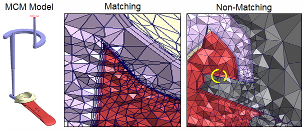
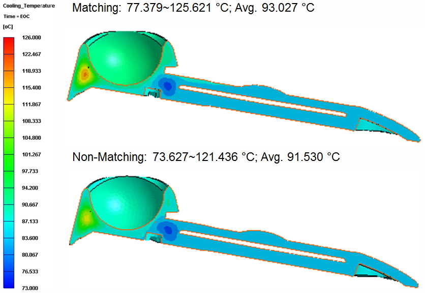
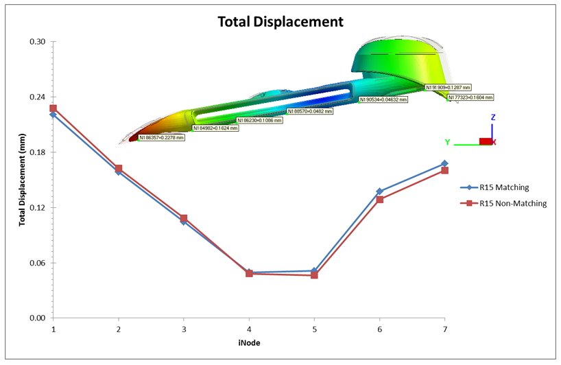
Also, the extended non-matching mesh technology supports the automatic meshing of mold components to be non-matched, such as the interface between part and part insert/mold base in order to obtain accurate simulation results with minimal effort.

Streamlining Simulation Workflow in One Integrated Platform
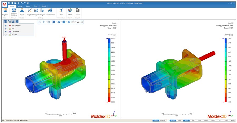
Moldex3D Studio is a fully integrated platform that streamlines all phases of the simulation workflow, from pre-processing to post-processing onto one intuitive, ribbon-style interface. The new platform complements the current Moldex3D Designer and Moldex3D Project applications and enables users to display and compare simulation results of multiple designs simultaneously to shorten the product development time.

03_One-Platform-to-Speed-Up-Simulation-Workflow-and-Efficiency

Obtaining Optimal Accuracy through Fully Coupled Process Simulation
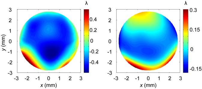
The fully coupled process simulation is a pioneering breakthrough in Moldex3D R15.0. Users can now take advantage of the new coupling technology which can simultaneously utilize Flow/Pack/Cool/Warp solvers to obtain optimal accuracy for simulating products of complex geometric designs or advanced manufacturing process like Rapid Heat Cycle Molding (RHCM).

Simulating New Process Applications
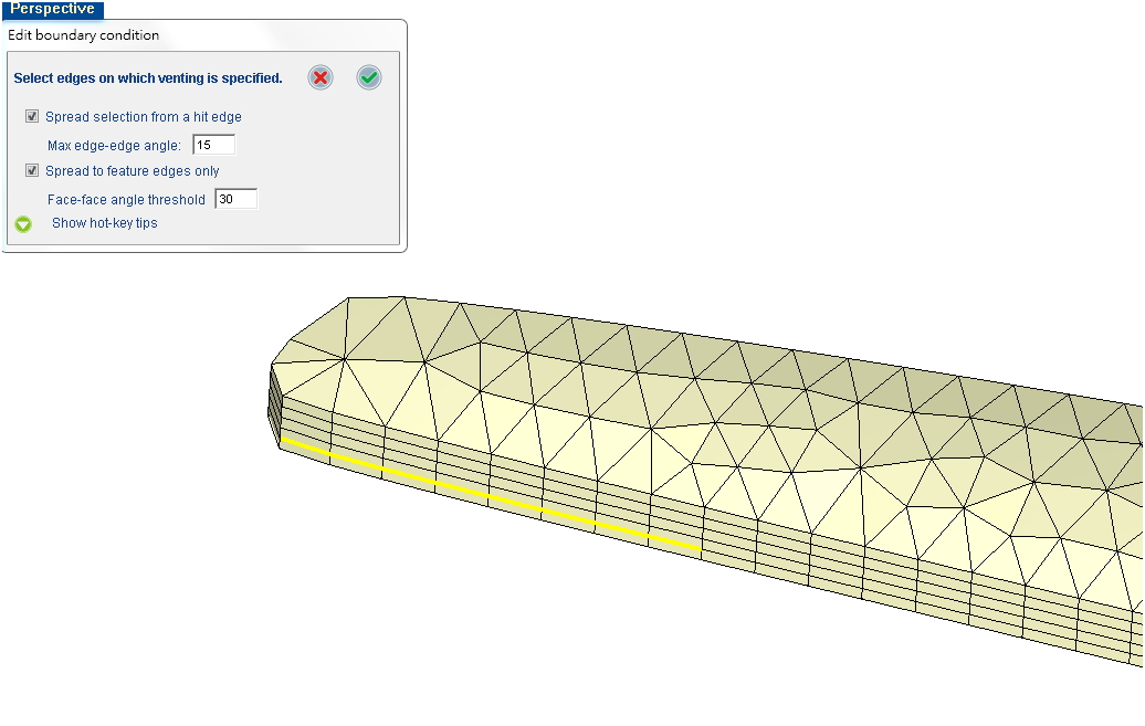
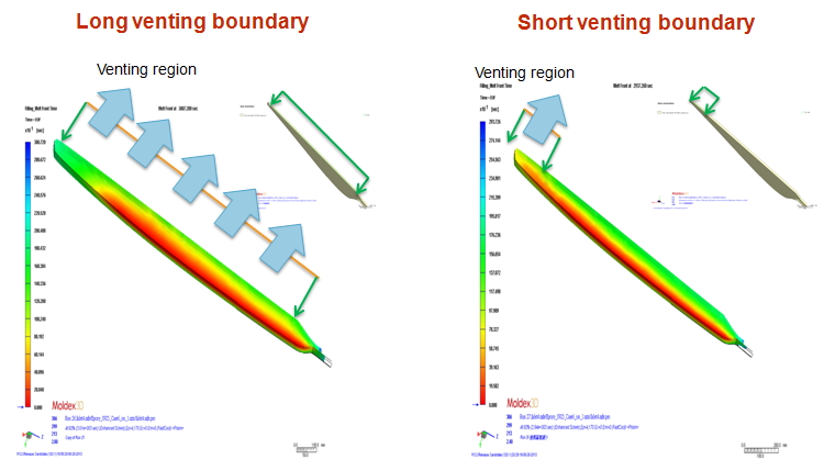
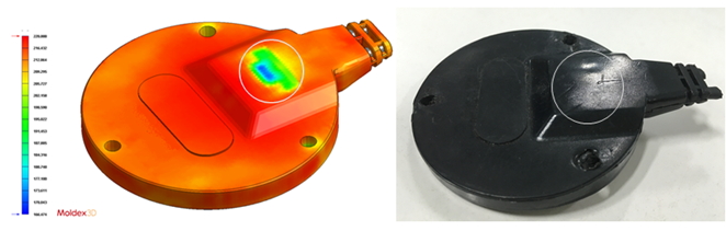
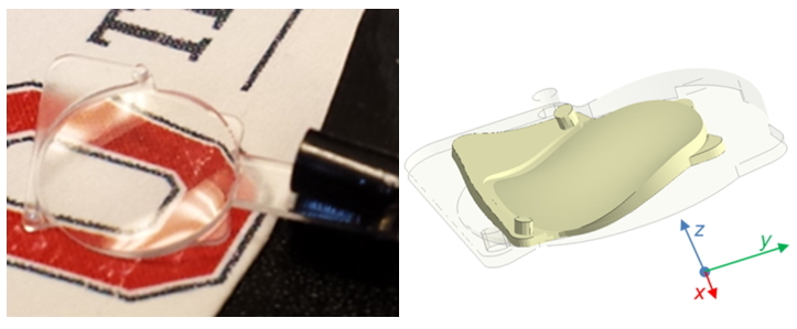
Moldex3D R15.0 also provides new simulation capabilities for In-mold Decoration (IMD) and Polyurethane (PU) chemical foaming process. The boundary condition application in the pre-processor of In-mold Decoration (IMD) simulation is made available the first time in commercial mold-filling analysis software to provide a quick and easy approach to meshing the decoration layers for simulation. Moreover, the “wash-out Index” feature enables designers to better predict washout of the ink of the decoration film to ensure successful decorative products.

The new addition of polyurethane (PU) foaming simulation supplements Moldex3D’s capabilities for chemical foaming processes; In addition to the existing microcellular foaming analysis for thermoplastics, PU foaming simulation provides part designers an ability to check the density distribution and ensure a desirable volume-to-weight ratio of the final part.

In addition, the enhancements in compression molding analysis enable a more accurate simulation for SMC materials, going from solid to molten and back to solid state, through a tighter integration between Moldex3D and LS-DYNA.

Bridging the Gap between Simulation & Shop Floor
The machine interface are further expanded to include over 15 mainstream injection molding machine manufacturers to shorten the gap between the predicted and real-life parameters.

Managing the Big Data for Effective Simulations
The new Intelligent Simulation Lifecycle Management (iSLM) solution provides an effective management of vast volumes of simulation data, giving teams at different geographic locations within an organization one single point of entry to store, share, and re-use simulation data in a safe and centralized environment.

“Moldex3D is devoted to improving its software’s functionality and simulation accuracy in each release,” said David Hsu, President of Product Development at Moldex3D. “With the new features and enhancements in Moldex3D R15.0, we aim to provide a high-performing CAE analysis with greater accuracy and efficiency to help users design and manufacture high-quality plastic parts with faster turnaround times which truly gives them an ability to keep an edge over competition and achieve excellent results.”

Moldex3D R15.0 is available now. For pricing and detailed product features, please contact your local resellers or sales representatives. Further information about Moldex3D R15.0 also can be found on the Moldex3D R15.0 Launch Page.

About CoreTech System (Moldex3D)
CoreTech System Co., Ltd. (Moldex3D) has been providing the professional CAE analysis solution “Moldex” series for the plastic injection molding industry since 1995, and the current product “Moldex3D” is marketed worldwide. Committed to providing advanced technologies and solutions to meet industrial demands, CoreTech System has extended its sales and service network to provide local, immediate, and professional service. CoreTech System presents innovative technology, which helps customers troubleshoot from product design to development, optimize design patterns, shorten time-to-market, and maximize product return on investment (ROI). More information can be found at www.moldex3d.com.

Webinar: Simulation of In-mold decorating (IMD) Process

$
0
0

2017-webinar-series-web-en

Webinar: Simulation of In-mold decorating (IMD) Process

In-mold Decoration (IMD) is a preferred process for a wide range of decorating plastic products, ranging from food containers, electronic devices to automotive interiors. IMD process offers a number of advantages over traditional decorative processes, including cost effective, efficiency and greater design flexibility. By inserting a decorative film into a plastic mold during the molding process, IMD process can help save a great deal of time and effort spent on tedious post-molding printing steps.

Moldex3D offers simulation solutions tailored to IMD process that can help determine optimum processing conditions and utilize the full capabilities of IMD process. In Moldex3D’s latest version, the new “Wash-out Index” feature allows product designers to predict the ink washout problem to ensure successful decorative products.
Attend this webinar to learn how Moldex3D simulation can help:

  • Capture the interplay between the film and the part during the injection molding process
  • Predict potential molding defects, such as ink washout, warpage, sink marks, weld lines, air traps, etc.
  • Optimize process conditions
    – Melt and mold temperature
    – Injection speed

Registration

We’re offering two sessions for this webinar, so be sure to attend the one that best fits your schedule! Calculate your time zone by clicking here.

Wednesday, May 17, 2017 10:30 AM CEST/2:00 PM IST Register now

Wednesday, May 17, 2017 2:30 PM EDT Register now


20170517-1

20170517-2

Webinar: Visualizing Flow Imbalance in Multi-cavity Systems

$
0
0

2017-webinar-series-web-en

Webinar: Visualizing Flow Imbalance in Multi-cavity Systems

One of the common challenges mold designers hoping to eliminate or overcome is flow imbalances in multi-cavity tools. However, without a dedicated analysis tool, it’s difficult to quickly identify the causes of flow imbalances. Moldex3D simulation technology provides True 3D visualization tools to help mold designers accurately visualize shear heating in runner systems so as to predict potential filling problems in early design phase without multiple tryouts. In addition, Moldex3D can further help mold designers evaluate the effects of mold design, material characteristics and flow rate for designing a better multi-cavity mold.

Webinar Highlights

  • Investigate the causes of non-uniform filling in multi-cavity injection molding systems
  • How Moldex3D can help simulate and minimize shear-induced imbalances
  • Overcome the imbalances in multi-cavity co-injection molding

Registration

We’re offering two sessions for this webinar, so be sure to attend the one that best fits your schedule! Calculate your time zone by clicking here.

Wednesday, May 31, 2017 2:30 PM EDT Register now

Thursday, June 1, 2017 10:30 AM CEST/2:00 PM IST Register now


 20170531

CHINAPLAS 2017

$
0
0

CHINAPLAS, recognized as the biggest plastics and rubber exhibition in Asia and the second in the world by plastic industry, will hold its 31th edition in 2017. CHINAPLAS 2017 rotates back to China Import & Export Fair Complex, Pazhou, Guangzhou, PR China on 16-19 May. With the theme of “Green Innovation for a Smart Future”, CHINAPLAS proposes a series of comprehensive applications for senior-level, professional visitors which especially focusing on “Intelligent Manufacturing”, “High-tech Materials” and “Green Solutions”.

This year at CHINAPLAS 2017, Moldex3D will demonstrate our latest CAE simulation technologies and showcase current and future industry trends. We cordially invite you to stop by our Booth (Hall 5.2 J41) and find out the best solution for helping you excel in today’s competitive global climate.

chinaplas-2017-booth1

chinaplas-2017-booth2

Venue

China Import & Export Fair Complex, Pazhou, Guangzhou, PR China

IF

Moldex3D Extends Non-matching Mesh Technology to Connect Part & Part Insert /Mold Base

$
0
0

Date | 2017/04/24

Multi-Component Molding (MCM) has been popularly used for producing complex parts in a variety of industries, including electronics, consumer products, and automotive. This technology offers an innovative approach to combine several components inside the mold by eliminating the need for post-molding assembly, bonding, or welding as well as reducing the overall manufacturing cost. This process also promotes design flexibility and improves part aesthetics, value, quality, and functions. The first component known as part insert, is pre-placed in the cavity to be subsequently over-molded by the polymer melt. In general, part insert can be made of either a pre-molded plastic or metal. Therefore, it is commonly known as either over-molding or insert molding, respectively. To prepare a good mesh model that incorporates part insert can be challenging when accurate analysis results are aimed to be attained at the same time.

Moldex3D Multi-Component Molding (MCM) provides a powerful simulation tool for both over-molding and insert molding as well as a robust pre-processor to automatically generate surface and solid meshes of the part, part insert, mold base, and other molding components. In the previous version, Moldex3D R14.0 supports non-matching mesh topology at the contact faces between part and part insert through which the analysis could have continuous results across the non-matching mesh boundary. As a result, users could save lots of time and effort in completing the mesh preparation without bothering matching the mesh elements. Moldex3D R15.0 further extends the functionality of this non-matching feature by allowing users to generate a solid mold base for the model with non-matching part and part insert (Fig. 1). Thus, it provides two other benefits besides faster mesh preparation: more accurate results for cases that are typically dependent on fine solid mold base mesh resolution and faster solver calculation by which solver does not need to auto-partition the mold base mesh.

moldex3d-extends-non-matching-mesh-technology-to-connect-part-part-insert-mold-base-1
Fig. 1 Moldex3D R15.0 supports both matching and non-matching mesh models; solid mold base can be generated in non-matching model.

Following is a case study of generating a solid mold base using non-matching feature for an over-molding model.. Both part and part insert materials were PC+ABS, and the melt temperature, mold temperature, and initial part insert temperature were 265 °C, 75 °C, and 30 °C, respectively. The results from matching mesh model were used as the reference for the non-matching mesh model. The temperature profile and the Z-displacement were evaluated. The simulation result of the non-matching mesh model is similar to the result from the matching mesh model (Fig. 2 and 3). This indicates that solid mold base in non-matching mesh model can work well.

moldex3d-extends-non-matching-mesh-technology-to-connect-part-part-insert-mold-base-2
Fig. 2 Comparing temperature results between Matching mesh and Non-matching mesh models.
moldex3d-extends-non-matching-mesh-technology-to-connect-part-part-insert-mold-base-3
Fig. 3 Matching and non-matching mesh models yield close Z-displacement results.

Moldex3D offers more advanced non-matching mesh technology. It promotes easier and faster mesh preparation with its available non-matching feature and allows users to generate a solid mold base for this non-matching mesh model that can lead to more accurate results and faster calculation from a  solver’s point of view at the same time. Hence, this innovative technology can further enhance the benefits of typical MCM analysis.


Webinar: Evaluating Hot Runner Systems to Improve Tool Quality

$
0
0

2017-webinar-series-web-en

Webinar: Evaluating Hot Runner Systems to Improve Tool Quality

As the product design continues to advance in modern product development process, so does the design of a hot runner system; the more complex the hot runner design is, the more time it needs for attaining a detailed Advanced Hot Runner analysis.

In this webinar, we will introduce Hot Runner Steady (HRS) Analysis- an innovative simulation technology that directly addresses the troublesome flow balance issue in today’s complex hot runner system designs. With that, users can fully examine and optimize all aspects of their hot runner design, which ultimately leads to a successful hot runner design.

Webinar Highlights

  • Hot Runner Applications & Simulations
  • Hot Runner Steady Analysis
  • Case Study

Registration

We’re offering two sessions for this webinar, so be sure to attend the one that best fits your schedule! Calculate your time zone by clicking here.

Wednesday, June 14, 2017 10:30 AM CEST/2:00 PM IST Register now

Wednesday, June 14, 2017 2:30 PM EDT Register now


hot runner technology component  hot runner temperature distribution

Webinar: Identifying Optimal Design Parameters for Injection-molded Parts

$
0
0

2017-webinar-series-web-en

Webinar: Identifying Optimal Design Parameters for Injection-molded Parts

Injection molding is a very complex procedure that combines part and mold designs, materials, and process conditions. Each factor has a great impact on the final part quality. Getting the right combination of all factors requires trial-and-error, which consume a lot of time and money. Moldex3D Expert is a powerful tool that can help evaluate and optimize process design using statistical Design of Experiments. Determining the optimum conditions for any given part / mold design will help achieve better part quality before even going to the mold.

Webinar Highlights

  • Overview of Moldex3D Expert- Powerful Design-of-Experiments Analysis
  • Key Benefits and Features to Help Users Obtain Optimum Process Conditions
  • Case Study

Registration

We’re offering two sessions for this webinar, so be sure to attend the one that best fits your schedule! Calculate your time zone by clicking here.

Wednesday, June 28, 2017 10:30 AM CEST/2:00 PM IST Register now

Wednesday, June 28, 2017 2:30 PM EDT Register now


moldex3d design of experiments

Predict Filling Behavior in Resin Transfer Molding Through Simulation Tool

$
0
0

Date | 2017/04/24

Resin Transfer Molding (RTM) is one of the manufacturing methods used to produce Fiber-reinforced plastics (FRP) products. These have been widely used in aircraft and automotive parts because of their high-strength and durable-stiffness material properties. In RTM process, the dry fiber mat is placed in the cavity first, and the thermoset resin is then injected into the cavity.

The biggest challenge in RTM process is to select the appropriate inlet and venting locations in order to avoid flow imbalance. Since the values of anisotropic permeability in the fiber mat and the fluid viscosity both increase over time, it’s difficult to predict the complicated filling behavior of the resin without a 3D simulation tool. Therefore, users can utilize Moldex3D Resin Transfer Molding (RTM) to visualize the filling behavior in order to optimize the process and make mold design modifications before production.

Moldex3D’s Resin Transfer Molding (RTM) is a 3D CAE module for simulating Resin Transfer Molding process. The RTM module has a smart and user-friendly wizard to help users assign RTM parameters and is able to provide accurate filling/curing analysis results. The following steps help users to properly set the process conditions for Resin Transfer Molding simulations.


Step 1: Create a new project, select the 3D Solid Model Solver, and choose the Resin Transfer Molding module.

predict-filling-behavior-in-resin-transfer-molding-through-simulation-tool-1 predict-filling-behavior-in-resin-transfer-molding-through-simulation-tool-2


Step 2 Filling Settings:
In the Process Wizard, the filling process of Injection Molding module is controlled by the filling time, while the RTM filling process is controlled by the flow rate and the pressure. There are two types of filling settings for a RTM analysis: By Flow Rate and By Pressure.

predict-filling-behavior-in-resin-transfer-molding-through-simulation-tool-3 predict-filling-behavior-in-resin-transfer-molding-through-simulation-tool-4

  • By Flow RateUse Maximum inlet flow rate and assign the flow rate profile in Profile setting.
  • By Pressure: Use Maximum injection pressure and assign the pressure profile in Profile setting.

Also, users can set Maximum filling time for a termination timing of filling analysis, and set Resin temperature and Mold temperature to control the temperature distribution during the filling process.

predict-filling-behavior-in-resin-transfer-molding-through-simulation-tool-5


Step 3 Curing Settings:
In this tab, users can specify the curing switch timing and the pressure.

Users can specify another curing switch timing through By volume(%) filled, and the curing switch-over will occur as the cavity is filled with a user-defined percentage. Otherwise, when By filling time(sec) is selected, the curing switch-over will occur at the user-defined time.

On the other hand, the curing pressure is controlled by the reference pressure and the pressure profile and the curing analysis will end at the given Curing time. Select reference curing pressure between End of filling pressure and Maximum curing pressure, and assign the pressure variation profile by clicking the Curing pressure profile.

predict-filling-behavior-in-resin-transfer-molding-through-simulation-tool-6 predict-filling-behavior-in-resin-transfer-molding-through-simulation-tool-7


Step 4: Prior to running a RTM analysis, Venting boundary condition has to be set. Launch Designer workspace to set the RTM boundary condition, click Setting under the RTM tab in Computation Parameter, and users can then define the venting condition.

predict-filling-behavior-in-resin-transfer-molding-through-simulation-tool-8


Step 5 In the workspace, click Add venting BC and select the location of the venting BC. The faces near the venting selected location will be defined as venting BC. Click predict-filling-behavior-in-resin-transfer-molding-through-simulation-tool-9 when it is done. After finishing the process, venting BC, and other project settings, users can then launch the filling and curing analysis.

predict-filling-behavior-in-resin-transfer-molding-through-simulation-tool-10predict-filling-behavior-in-resin-transfer-molding-through-simulation-tool-11


Filling patterns with different lengths of venting boundary
Venting is an important factor in RTM process. In the filling stage, the resin flows from the inlet to the venting boundary. Different lengths of the venting boundary condition will result in different flow behaviors as shown below.

predict-filling-behavior-in-resin-transfer-molding-through-simulation-tool-12

Solving Aesthetic Issues of Electronic Component Insert Molding through Moldex3D

$
0
0

Date | 2017/04/25

Solving Aesthetic Issues of Electronic Component Insert Molding through Moldex3D

Customer Profile
 skf

SKF has been a leading global technology provider since 1907. Their fundamental strength is the ability to continuously develop new technologies – then use them to create products that offer competitive advantages to our customers. We achieve this by combining hands-on experience in over 40 industries with our knowledge across the SKF technology platforms: bearings and units, seals, mechatronics, services and lubrication systems. Our success is based on this knowledge, our people, and our commitment to SKF Care principles. (Source: http://www.skf.com/in/our-company/index.html)

Executive Summary

Every industry has its unique challenges, but virtually all industries share the goals of increased machine uptime, reduced maintenance, improved safety, energy savings and lower total cost of ownership. With expertise in a wide range of disciplines and decades of experience as a technical partner to both equipment manufacturers and end users in every major industry, SKF is delivering not just products but total integrated solutions that help our customers achieve their goals.

The SKF sensor unit in this case includes electronics that need adequate sealing mainly for preventing liquid ingress and mechanical protection. This can be achieved by potting and over molding.  The project involves analyzing the over molding of electronics, connectors and cable with printed circuit board (PCB) material as inserts.

Challenges

  • To reduce design iteration and prototyping times.
  • Identify the defects and correlate the simulation results with actual product failures for design optimization.
  • Reduce product development cycle time.

Solutions

Moldex3D Designer and Project helped to create BLM mesh and run simulation successfully. Moldex3D technical support team helped to explore the tool and fix the problems whenever required in minimum time. As SKF has inserts with small electronic components, cable, connector’s etc., achieving good quality mesh was a big challenge. This was achieved using BLM mesh tool as recommended by Moldex3D team.

Benefits

  • Optimized the process parameters.
  • Identified defects and suggested improvement with respect to design modification and process settings.
  • The simulation results helped to investigate the reason for product failure.

Case Study

In the first phase, the objective was to carry out low pressure over molding simulation for single cavity molding. With current process setting identification of design and process defect was one of the main requirements. The observation must be made to find correlation with the existing manufactured part. Phase 2 objective was to realize a rheology over molding study to check the feasibility of molding 2 parts of the same product and define the best position of the injection point, best runner and gate design and dimension of cooling circuit. At the same time, the defect identified in the 1st phase must also be fixed.

The technical centre of SKF used Moldex3D Advanced solution to simulate the molding scenario of the original design. The meshing issue of the small electronic component and cavity was solved by BLM meshing. Through Moldex3D simulation results, they found filling issues in some regions on the part due to the gate location. There was also flow hesitation in thin wall areas. In addition, SKF was able to identify the internal residual stresses on the electronics during molding process. Finally they were able to optimize the process parameters to get the best cycle time and operate at the lowest possible pressure.

There was a design change in the gate type and location of the 2-cavity mold design. The runner system dimension and design was also changed respectively taking into account the defect observed in the first phase. This resulted in smooth material flow without hesitation effect and filling was better compared to the existing design (Fig. 1). The process was optimized to achieve the best cycle time with reduced cost and operated at low pressure. These were done by performing various runs and then compare the graph to finalize the best solution. Simultaneously, the temperature, pressure and thermal residual stresses around the electronic component were also controlled.

solving-aesthetic-issues-of-electronic-component-insert-molding-through-moldex3d-1
Fig. 1 We can observe the flow is not uniform in the original design (left) and there is flow hesitation in some areas like connector area. In new proposal (right) with 2 gates, we can observe the flow is uniform and the flow hesitation has almost been eliminated.

The simulation was generated for the existing design with the help of Moldex3D. All the observation was noted and the action plan was created with respect to process changes and design changes. The results obtained from simulation for the existing design were close to the real scenario. This was verified with the process data sheet from the production. The identified defects in the existing design were also observed in the existing product as shown in Fig. 2. After the design changes, Moldex3D was used to simulate both the original design and the optimized design. The design was optimized taking into account all the identified problems from the existing design. Additionally, the cycle time was optimized to reduce production time and cost. When compared with the actual mold trial results, SKF’s technical centre found that Moldex3D simulation analysis results had strong correlation with the real scenario.

solving-aesthetic-issues-of-electronic-component-insert-molding-through-moldex3d-2
Fig. 2 High correlation between simulated and actual manufactured part is shown. A sink mark is identified on the simulated model (left) and the same result is visible in the prototyped part (right).

Results

Through Moldex3D analysis, SKF could clearly understand the filling behavior and predict probable defects due to process parameters and design deviations prior to prototyping and production. This saved a large, valuable amount of product development cycle time due to early investigation using Moldex3D tool. The accuracy of Moldex3D simulation analysis was verified with the actual manufacturing process sheet and visual inspection. The result helped their technical centre to optimize the process parameters, identify and fix defects in product and also correlate the cause of product failures at end application with the identified defects.

Moldex3D Transfer Molding Simulation Introduction

$
0
0
  • Course Name: Moldex3D Transfer Molding Simulation Introduction
  • Date: June 06-07, 2017
  • Location: Farmington Hills, MI

register-now

Course Schedule

Day 1 Day 2
9:00 AM – 12:00 PM
  • Trainer / Trainee Introductions
  • Overview of Moldex3D
  • BLM Preparation
    – Overview of Designer Compression
    – Generate BLM
    – Auto-Generate Compression Zone
  • Look at Filling Results
    – Filling Interpretation
  • Rhino Preparation Practice
    – Generate BLM
    – Generate Compression Zone in Rhino
    – Generate Charge in Rhino
Lunch
1:00 PM – 4:00 PM
  • Rhino Preparation
    – Overview of Rhino compression
    – Workflow
    – Import BLM mesh
    – Generate Compression Zone
  • Set up & Launch Filling Simulation
  • Q&A
  • Rhino Preparation Practice
    – Continued from above….
  • Questions about Rhino
  • Q&A

Expense

  • $3,000 USD

Payment Method

  • Check
  • Cash
  • Credit Card (Visa and MasterCard)

Location


View Larger Map

Moldex3D Northern America, Inc.
27725 Stansbury Blvd., Suite 190,
Farmington Hills, MI 48334


Contact

Ms. Susan Vaaler


Registration Form

[contact-form-7]

Moldex3D and Stratasys Collaborate for New White Paper on Validating 3D Printed Injection Molds

$
0
0

Hsinchu, Taiwan– Apr 26, 2017– The growing adoption of 3D printing technology offers new alternatives for creating injection mold prototypes cost-effectively and quickly using 3D Printed Injection Molds (3DPIM). But without a dedicated validation tool, part designers and mold builders might not reap the full benefits of 3DPIM. To help mitigate risk of 3D printed injection mold production, CoreTech System (Moldex3D), the world’s leading provider of plastic injection molding simulation solutions, and Stratasys – the 3D printing and additive manufacturing solutions company – have collaborated to release a new white paper entitled, “Demonstration of an Effective Design Validation Tool for 3D Printed Injection Molds (3DPIM).” The paper presents advantages of using upfront simulation to assess and improve the moldability of 3D printed injection molds.

This joint white paper discusses opportunities and challenges of generating injection mold prototypes with 3D printing methods, and how Moldex3D injection molding simulation software is a viable solution for 3DPIM design validation and optimization. By applying Moldex3D simulation analyses, product designers and molders can accurately predict mold performance, validate design decisions and take corrective actions to avoid costly mistakes that might occur in final production. The solution will enable high-quality and high-performance prototypes to create better final production parts.

“Moldex3D is a powerful simulation tool to help evaluate the performance of 3D printed injection molds. Combining Stratasys 3D printing with Moldex3D simulation software, customers have an enhanced solution for validating and testing thermoplastic parts and molds for fast and inexpensive production,” added Gil Robinson, Head of Molding Use Case at Stratasys.

Using Moldex3D to predict unbalanced flow in a 3D printed injection mold by Stratasys

“Simulation has increasingly permeated many aspects of product development process, from initial concept design, prototyping to production,” said Venny Yang, President at Moldex3D. “For part designers and mold builders looking to take advantage of rapid prototyping with 3D printed injection molds, we believe Moldex3D’s upfront simulation capabilities can not only to help them better understand the complex nature of injection molding process, but also to bridge the gap between prototyping and final production.”

The white paper also includes a case study which provides valuable examples of how Moldex3D’s simulation technology can be used to predict, validate and optimize the design of 3D printed injection molds. To download the full white paper, please visit: http://www.moldex3d.com/en/products/stratasys-white-paper

About CoreTech System (Moldex3D)
CoreTech System Co., Ltd. (Moldex3D) has been providing the professional CAE analysis solution “Moldex” series for the plastic injection molding industry since 1995, and the current product “Moldex3D” is marketed worldwide. Committed to providing advanced technologies and solutions to meet industrial demands, CoreTech System has extended its sales and service network to provide local, immediate, and professional service. CoreTech System presents innovative technology, which helps customers troubleshoot from product design to development, optimize design patterns, shorten time-to-market, and maximize product return on investment (ROI). More information can be found at www.moldex3d.com.

Partners from 22 Countries Attended Moldex3D FY’17 EMEA Channel Partner Meeting

$
0
0

Hsinchu, Taiwan– May 03, 2017–Moldex3D FY’17 EMEA Channel Partner Meeting organized by CoreTech System (Moldex3D) has just been held in Utrecht, The Netherlands on April 19 and 20. Channel partners from 22 countries attended this meeting and brought valuable experience and feedback about the EMEA market. Through this interaction and communication with the partners, Moldex3D was able to attain a better understanding about our European customers’ needs. The great success of this meeting reinforces that Moldex3D has become a well-received and reliable international brand.


“Moldex3D Europe office has just been established in Utrecht, the Netherlands. Moldex3D FY’17 EMEA Channel Partner Meeting also took place in the same country, showing our ambition to enhance Moldex3D’s technical support level in Europe,” said Dr. Venny Yang, President at Moldex3D. “We have received lots of positive feedback about this meeting from our partners. It indicates we have further strengthened our market position in EMEA area,” said Dannick Deng, Managing Director of EMEA.

The topics of this meeting contain technical as well as industrial aspects including the introduction of this year’s release Moldex3D R15.0, sales and marketing strategies, and competitor information. “This is the most fulfilling Channel Partner Meeting that I have participated in!” said Teresa Neves at Simulflow from Portugal, a ten-year partner of Moldex3D. Many of Moldex3D’s partners also pointed out the great success of Moldex3D R14.0, the 2016 version of CAE software for injection molding, among European customers. They are looking forward to the outstanding performance of Moldex3D R15.0.

Moldex3D particularly appreciates the channel partners who were invited to share their successful sales experiences in this meeting. The sessions provided by Fabien Buchy at SimpaTec SARL from France, Remco Boer at Protyp from the Netherlands and Peer Guldbrandsen at FlowHow® APS from Denmark enabled the attendees to learn from each other’s experiences and develop new ideas.

Moldex3D EMEA Team concludes, “By communicating with our channel partners face to face and understanding the thoughts and needs of our customers, Moldex3D will have better understanding on how we can further improve our product and technology to fulfill and exceed the market demands.”


About CoreTech System (Moldex3D)
CoreTech System Co., Ltd. (Moldex3D) has been providing the professional CAE analysis solution “Moldex” series for the plastic injection molding industry since 1995, and the current product “Moldex3D” is marketed worldwide. Committed to providing advanced technologies and solutions to meet industrial demands, CoreTech System has extended its sales and service network to provide local, immediate, and professional service. CoreTech System presents innovative technology, which helps customers troubleshoot from product design to development, optimize design patterns, shorten time-to-market, and maximize product return on investment (ROI). More information can be found at www.moldex3d.com.


Webinar: Advanced Meshing Techniques in Moldex3D

$
0
0

2017-webinar-series-web-en

Webinar: Advanced Meshing Techniques in Moldex3D

A high-quality mesh is a prerequisite for accurate and reliable plastic injection molding simulation results. In this webinar, Moldex3D expert will demonstrate the latest developments in Moldex3D meshing technology, and share tips on how to leverage these advanced meshing tools to greatly reduce pre-processing time and effort while maintaining a fine balance between accuracy and speed.

Webinar Highlights

  • Moldex3D Meshing Solutions
  • Features and Benefits of Moldex3D Designer BLM
  • Q&A

register-now


Registration

We’re offering two sessions for this webinar, so be sure to attend the one that best fits your schedule! Calculate your time zone by clicking here.

Wednesday, July 12, 2017 10:30 AM CEST/2:00 PM IST Register now

Wednesday, July 12, 2017 2:30 PM EDT Register now


Plastteknik Nordic 2017

$
0
0

Moldex3D is pleased to announce that together with our local partners, FlowHow and PESAB, we will be exhibiting at Plastteknik Nordic 2017 in Sweden from 17th to 18th in May. Here you are guaranteed to find what you need for your product idea and get inspired by the latest technology trends. Please come visit us at our booth D09, bring your questions, talk with our Moldex3D professionals and see how Moldex3D can help you with your plastic part design and manufacturing!

Venue

MalmöMässan
Mässgatan 6, 215 32 Malmö, Sweden

Event Contact

Vera Yeh
E-mail: verayeh@moldex3d.com
+886-3-5600199 ext. 707


Moldex3D Users’ Meeting- Simulflow 2017

$
0
0

Moldex3D along with our local partner Simulflow is excited to invite you to our Users’ Meeting on 31st May at Hotel Villa Batalha in Portugal. It’s a great opportunity to network with industry experts and learn the best practices for leveraging Moldex3D simulation tools to overcome your daily design challenges.

In this year’s event, Moldex3D professionals will showcase the latest powerful features of Moldex3D R15 version and also you will learn how to solve plastic injection molding problems from case studies and demonstration presented by our users and experts. Mark your calendar now and get ready for your next winning product. Look forward to seeing you there!

Registration

For registration and more information, please contact via geral@simulflow.pt.

Agenda

Time Subject Speaker
9:00-9:30 Registration Simulflow
9:30-9:45 Welcome Simulflow
9:45-10:15 R15 Lightweight Solutions Alfin Chen
CoreTech
10:15-11:00 What is new in R15 Teresa Neves
Simulflow
11:00-11:30 Coffee break
11:30-12:30 Hot runner systems : layout definition, hot runner dimensioning and new technology activeGate® Control Systems Suzette Izidoro,
Rui Brandão e Rui Manso
Synventive
12:30-14:00 Lunch
14:00-15:00 Workshop about R15 Alfin Chen
CoreTech
15:00-15:30 Tips: hot runners, sequential injection; warpage results interpretation Teresa Neves
Simulflow
15:30-16:15 Simulating Thermoplastic Chemistry
SABIC Introduction; Engineering Thermoplastics; Material Characterization
Francisco Papis
SABIC
16:15-16:30 Coffee break
16:30-17:00 Users presentation  
17:00-17:30 Product Roadmap: What’s Next? Alfin Chen
CoreTech
17:30-17:45 Closure Simulflow

Venue

Hotel Villa Batalha
Rua D. Duarte I, 248, 2440-415 Batalha, Portugal

Contact

Teresa Neves
Email: geral@simulflow.pt
TEL: +351-244-825-859

Vera Yeh
E-mail: verayeh@moldex3d.com
TEL:+886-3-5600199 ext. 707

Interplas Thailand 2017

$
0
0

Moldex3D มีความยินดีที่จะประกาศให้ทราบว่า ทางบริษัทจะจัดแสดงสินค้าในงาน Interplas Thailand 2017 ณ BITEC กรุงเทพมหานคร ประเทศไทย งาน Expo จะจัดขึ้นตั้งแต่วันที่ 21-24 มิถุนายน 2017 และบูธของเราตั้งอยู่ที่ Hall 99 หมายเลขบูธ 8M30 โดย Moldex3D ยินดีเป็นอย่างยิ่งที่ได้มีส่วนร่วมในงานแสดงสินค้าสำหรับอุตสาหกรรมพลาสติกระดับนานาชาติที่ใหญ่ที่สุดในประเทศไทยประจำปีนี้

ในงานแสดงสินค้าครั้งนี้ เราจะแสดงให้เห็นถึงเทคโนโลยีการจำลองใหม่ล่าสุดจาก Moldex3D และเสาะหาโซลูชั่นที่เป็นไปได้เพื่อช่วยท่านในการออกแบบและผลิตชิ้นส่วนพลาสติกให้ดีขึ้น โปรดมาเยี่ยมชมเราได้ที่ Hall 99  หมายเลขบูธ 8M30 และมาค้นพบสิ่งที่เราสามารถช่วยท่านได้ในโลกของวิศกรรมพลาสติก ณ ปัจจุบันที่เต็มไปด้วยการแข็งขัน

ข้อมูลงาน Interplas Thailand 2017
อินเตอร์พลาส ไทยแลนด์ 2017 งานเดียวที่อัดแน่นด้วยนวัตกรรมเครื่องจักรและเทคโนโลยีเพื่ออุตสาหกรรมการผลิตพลาสติกและปิโตรเคมี รวมถึงเครือข่ายระดับโลกที่คนในวงการต้องไม่พลาดหากต้องการเพิ่มศักยภาพกระบวนการผลิต ตั้งแต่การทำแม่พิมพ์ การเป่า การฉีด การรีด และการรีไซเคิลสำหรับการผลิตยานยนต์ อิเล็กทรอนิกส์ บรรจุภัณฑ์ และการแพทย์ ผู้ซื้อกว่า 17,000 รายจากหลายวงการจะได้พบกับประสิทธิภาพการผลิตที่เหนือกว่าจากกว่า 350 แบรนด์ จาก 20 ประเทศ พร้อมเปิดรับโอกาสทางธุรกิจที่เข้มข้นจากกิจกรรมการตลาดและการเสริมสร้างเครือข่ายทั้งช่วงก่อนและระหว่างงาน งานนี้เป็นงานประจำปีที่ครบวงจรที่คนในวงการอย่างท่านต้องไม่พลาด

สถานที่

BITEC (Bangkok International Trade & Exhibition Centre)
88 Bangna-Trad Road (Km.1), Bangna, Bangkok 10260, Thailand

ติดต่อ

  • สอบถามเรื่องงานขายและข้อมูลทางเทคนิค ติดต่อคุณ Yiji Lin ได้ที่ yijilin@moldex3d.com
  • สอบถามเรื่องกิจกรรมและการตลาด ติดต่อคุณ Kate Chan ได้ที่ katechan@moldex3d.com

English Version

Moldex3D is delighted to announce that we will be exhibiting at Interplas Thailand 2017 in BITEC Bangkok, Thailand. The Expo will be held from June 21-24, 2017, and our booth is located at Hall 99, Booth #8M30. Moldex3D is happy to take part in this annual Thailand’s largest international exhibition for plastic industry.

At the exhibition, we will demonstrate the latest simulation technologies of Moldex3D and explore possible solutions to help you design and manufacture better plastic parts. Please come to visit us at Hall 99, Booth #8M30 and find out what we can do to help excel in today’s competitive plastic engineering world.

About Interplas Thailand 2017
“ InterPlas Thailand 2017 ” is only one event that can provide the plastics and petrochemical manufacturing industry with the latest machinery and technologies, new knowledge, and global networks that the industrialists need to speed up manufacturing processes with cutting-edge functions. From efficient injection moulding, blowing, extrusion to recycling for various applications from automotive, electronics, packaging to medical devices, 17,000+ quality buyers from more industry sectors who will discover the new level of productivity from over 350 brands from 20 countries. Indulge in more intensity of business opportunities through dedicated pre-show marketing and promotional activities as well as business-inducing networking programs. This is the most comprehensive annual trade show and industry community event you should not miss.

Venue

BITEC (Bangkok International Trade & Exhibition Centre)
88 Bangna-Trad Road (Km.1), Bangna, Bangkok 10260, Thailand

Contact

Webinar: How to Interpret Moldex3D Simulation Results

$
0
0

2017-webinar-series-web-en

Webinar: How to Interpret Moldex3D Simulation Results

In this webinar, our expert will be taking you on a deep dive into the anatomy of the post-processing stages of Moldex3D plastic injection molding simulation. This will give users the ability to correctly view and interpret the analysis results from the simulation program, allowing them to make informed decisions early in the product development cycle.

Webinar Highlights

  • Filling Analysis Result Interpretation
  • Packing Analysis Result Interpretation
  • Cooling Analysis Result Interpretation
  • Warpage Analysis Result Interpretation

register-now


Registration

We’re offering two sessions for this webinar, so be sure to attend the one that best fits your schedule! Calculate your time zone by clicking here.

Wednesday, July 26, 2017 10:30 AM CEST/2:00 PM IST Register now

Wednesday, July 26, 2017 2:30 PM EDT Register now


Viewing all 736 articles
Browse latest View live